The Pulse Width Modulation (PWM) plays an important role in controlling the a lot of circuits. If you want to control the speed of the motor, PWM plays a key role. Here, in our project, the PWM Technique is used for dimming the LEDs.
Using PWM technique, the mount of power delivered to a device is varied and hence, if we can control the pulse width of the signal, we can easily control the device like making a simple DC Motor to rotate slow or fast or to dim the intensity of an LED.
Block Diagram of LED Dimmer using 555
The following image depicts the block diagram of the PWM based LED Dimmer using 555 Timer IC. A 12V DC source is used to power the entire circuit including the 555 timer IC and the LEDs. The 555 timer is used to generate a PWM signal with the help of a few passive components. The generated PWM Signal is then applied to a bunch of LEDs and based on the Duty Cycle of the PWM Signal, the intensity of the LEDs can be high or low. Related Post: LED Lamp Dimmer Circuit
A Brief Note on 555 Timer IC
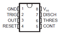
The 555 Timer is an 8-pin Integrated Circuit available in Dual-in-Line Package originally developed by Signetics. It is one of the most popular ICs and is used for a variety of applications like Timer, Oscillator and Pulse Generation. Pin Diagram of the 555 Timer IC is shown in the following image. The pin 8, which is the VCC pin, is used to give the main supply voltage to the IC. The operating voltage may vary from 3v to 15V. Pins 2, 6 and 7 are the Trigger, Threshold and the Discharge Pins.
Pin 4 is the Reset pin and it is used to reset the complete IC. It is an active LOW Pin. The output of the IC can be taken from the out pin i.e. the pin 3. Pin 5 is the Control Pin. The 555 Timer IC can work in three different modes of operation: Astable, Monostable and Bistable operations. It has features like timing for micro seconds through hours, adjustable duty cycles and ability work in various voltage levels etc. It has a wide range of applications like lamp dimmers, motor control, joysticks etc.
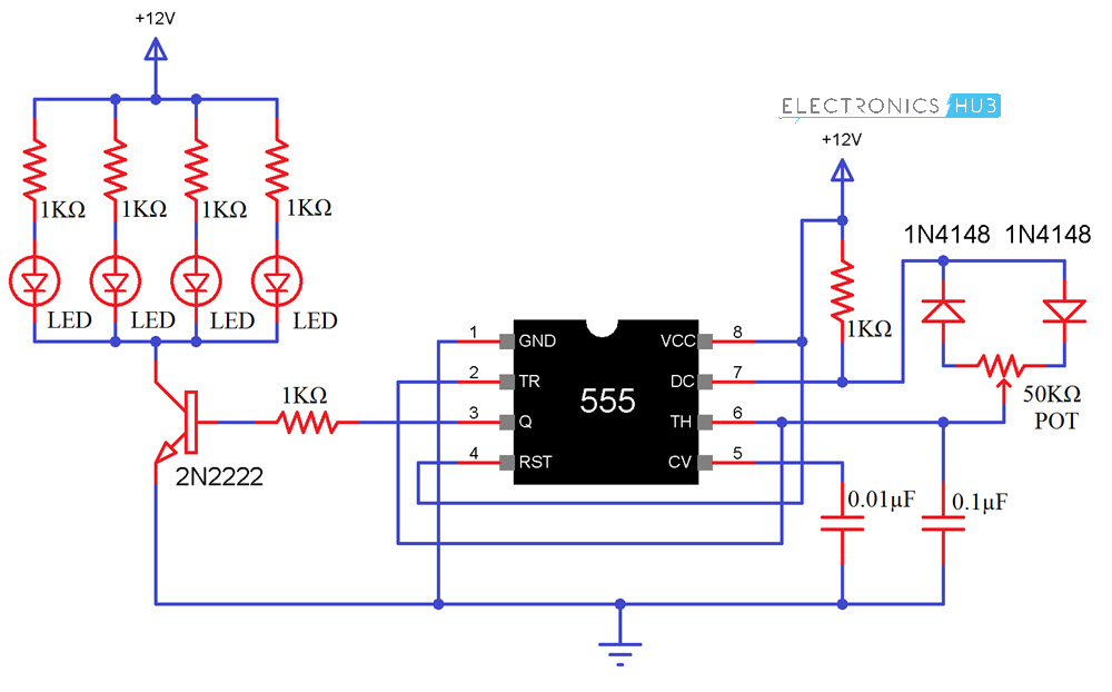
Circuit Diagram of PWM LED Dimmer Using 555
Components Required
555 Timer IC 1KΩ Resistor x 6 Red LEDs x 4 2N2222 NPN Transistor 0.1μF Capacitor 0.01μF Capacitor 50KΩ Potentiometer 1N4148 Diodes 12V Power Supply Mini Breadboard
Circuit Design
The 12V DC supply is given to the VCC Pin for operating voltage of 555 timer. The reset pin also directly connected to the 12V as shown in the circuit diagram. For resetting the IC, in case of an error while circuit is working, connect the RESET pin to GND for a Second and then connect it back to 12V. Pin 5 or the voltage control pin is not used in this application. Hence, a decoupling capacitor of 0.01μF is connected between pin 5 and GND. The Trigger pin (Pin 2) and threshold pin (pin 6) are shorted and the Wiper Terminal of the POT is connected here. Also, a 0.1μF Capacitor is connected between Pin 6 (or Pin 2) and GND. Now, one terminal of the POT is connected to anode of a Diode (preferably 1N4148) while the other terminal of the POT is connected to cathode of another diode. The other ends of both these diodes are connected to the Discharge Pin i.e. Pin 7. Also, a 1KΩ Resistor is connected between Pin 7 and VCC. The OUT pin is connected to the LED panel through the transistor.
Working of PWM LED Dimmer using 555
Here in this project, the 555 Timer is made to operate in the Astable Multivibrator Mode. The 1KΩ Resistor, the 50KΩ POT and the 0.1μF Capacitor connected with respect to Pins 2, 6 and 7 will play an important role. Based on the charge and discharge timings of the Capacitor, a PWM Signal is generated at the OUT Pin i.e. Pin 3 of the 555 Timer IC. The output of the 555, which is taken form pin 3, is connected to the led panel through the NPN Transistor (2N2222 is used here) and a 1KΩ resistor.
The 1KΩ resistor is used to limit the base current of the transistor and transistor is used as an amplifier to limit or enhance the current which is given to the LED panel. Related Posts:
Auto Night Lamp Using High Power LED Unbiased Digital Dice with LEDs
Comment * Name * Email * Website
Δ
![]()
![]()
![]()

![]()
![]()

