Traditional methods of solving these problems use fixed and mechanically switched series and shunt capacitors, reactors and synchronous generators. However, desired response has not been effective due to slow response, wear and tear of mechanical components.
With the invention of thyristor devices, power electronic converters are developed that led to implement FACTS controllers. These power electronic based controllers can provide smooth, continuous, rapid and repeatable operations for power system control. FACTS is an acronym for Flexible AC Transmission System and it is an application of power electronic devices to electrical transmission system. It is an AC transmission system that incorporates a power electronic controller and other static controllers to improve the controllability as well as power transfer capability. It improves the performance of electrical networks by managing active and reactive power. The IEEE definition for FACTS controller is stated as , it is a power electronic based system and other static equipment that provides the control of one or more AC transmission parameters (such as voltage, impedance, phase angle and power). The possibilities offered by the FACTS technology include
Power can be controlled for desired amount such that it flows through prescribed transmission routes Loading of the transmission lines near their thermal, steady-state and dynamic limits Enhancing the power transfer capability between interconnected transmission lines Increasing the quality of supply for sensitive industries Enhancing transmission system reliability and availability by limiting the impact of multiple faults
Why Compensation Techniques are used in Power system?
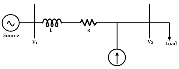
Power System network consist of three kinds of powers, namely, active, reactive and apparent power. Active power is the useful or true power that performs a useful work in the system or load. Reactive power is caused entirely by energy storage components and the losses due to reactive power may be considerable, although reactive power is not consumed by the loads. The presence of reactive power reduces the capability of delivering the active power by the transmission lines. And the apparent power is the combination of active and reactive power. In order to achieve maximum active power transmission, the reactive power must be compensated. This compensation is necessary for
Improving the voltage regulation Increasing system stability Reducing the losses associated with the system Improving the power factor Better utilization of machines connected to the system
The compensation techniques of the power system supplies the inductive or capacitive reactive power (to its particular limits) in order to improve the quality and efficiency of the power transmission system. The following are the two popular compensation techniques used in power system. [Also Read:Active, Reactive and Apparent Power ]
Shunt Compensation
In this type of reactive power compensation, various compensation or FACTS devices (which can be either switched or controlled) are connected in parallel to the transmission lines at particular nodes. These devices inject the current into the lines so that the reactive component of the load current is compensated thereby the losses are reduced and voltage regulation is improved. The types of shunt compensation devices include static synchronous compensator (STATCOM) and static VAR compensator (SVC).
Series compensation
In this, various compensation or FACTS devices (which can be either switched or controlled) are connected in series with the transmission lines at particular nodes. This compensation will give more control of power flow through the line and also improves the dynamic stability limit of the power system. Mostly, capacitors are installed in series with the lines. The amount of compensation is varied by installing several capacitor banks in series with the lines. This is achieved by thyristors controlled series capacitors. Thyristor controlled switched capacitors (TCSC) and fixed series capacitor (FSC) techniques are widely used for series compensation.
Types of FACTS Controllers
FACTS controllers are classified as
Shunt connected controllers Series connected controllers Combined series-series controllers Combined shunt-series controllers
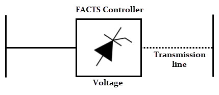
Series connected controllers
These controllers inject a voltage in series with the line. If this voltage is in phase quadrature with the current, the controller consumes or supplies variable reactive power to the network. These controllers could be variable impedance such as a reactor or capacitor or a power electronic based variable source. Examples of the series controllers include SSSC, TCSR, IPFC, TSSC, TCSC, and TCSR.
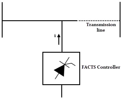
Shunt connected controllers
These controllers inject a current into the system at the point of connection. If this current is in phase quadrature with the line voltage, a shunt controller consumes or supplies variable reactive power to the network. Similar to the series connected controllers, these controllers could be a variable reactor or capacitor or a power electronic based variable source. Examples of the shunt controllers include TCR, STATCOM, TSR, TCBR and TSC.
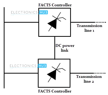
Combined series-series controllers
These controllers are the combination of individual series controllers that are controlled in a coordinated manner in multiple power transmission systems. Or these could be a unified controllers in which separate series controllers are employed in each line for series reactive power compensation and also to transfer the real power among the lines via proper link. Example of this controller is IPFC that balances the real and reactive power flow in the lines in order to maximize the power transmission.
Combined series-shunt controllers
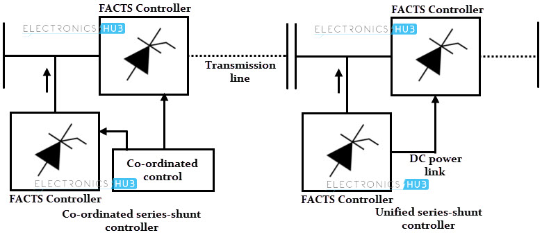
These are the combination of separate series and shunt controllers that are controlled in a coordinate manner or a unified power flow controller (UPFC) with series and shunt elements. These combined controllers inject current into the system with series part of the controller and voltage in series in the line with shunt part of the controller. Examples of these controllers include TCPST, UPFC and TCPAR.
Overview of 10 FACTS Devices or Controllers
In this section we will discuss above mentioned controllers in brief.
Static Var Compensator
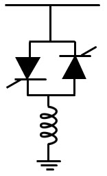
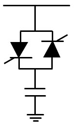
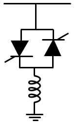
It is a shunt type controller which controls the power flow in transmission system and improves the transient stability of power grids. This controller regulates the voltage at its terminals by controlling the amount of reactive power injected into or absorbed from the power system. When the system voltage is low, SVC generates the reactive power and when the voltage is high it absorbs the reactive power. The reactive power is varied by switching the three phase inductor and capacitor banks. SVCs are basically thyristor controlled reactive power devices and common types of SVC are given below. It is a shunt connected static var absorber or generator. It consists of a fixed reactor in series with bidirectional thyristor switches. The impedance of this device varied in a continuous manner by varying the conduction angles of thyristors. The output of this device is adjusted to exchange either inductive or capacitive current. It maintains and controls the parameters (typically a bus voltage) of the power system. It is an alternative to STATCOM in terms of cost. It consists of a shunt connected capacitor which is connected in series with bidirectional thyristor switches. The impedance or reactance of this device is varied in a stepwise manner by controlling the thyristors either in a zero or full conduction operation. This controller offers no harmonics, no transients, and low losses.
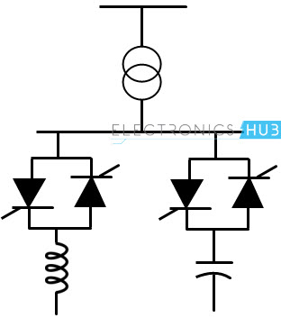
It is a special case of a TCR where phase control of the current is not exercised, instead the reactor is switched such that thyristors are either fully ON or OFF as in case of TSC. The advantage of TSR over TCR is that no harmonics current generation. Also, this controller use thyristors without firing control and hence lower cost and losses. The reactive compensation control in electric power system use the above stated SVC types in different configuration, such as combination of TCR and TSC, combination of TCR and TSC with filter circuit and TCR with filter circuit as shown in figure.
STATCOM
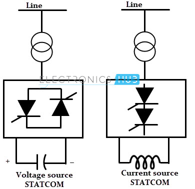
STATCOM means static synchronous compensator and it has the similar characteristics to that of synchronous condenser but it has no inertia as it is an electronic device. It consists of a solid state voltage source inverter coupled with a transformer and this arrangement is tied to a transmission line. This arrangement supplies or draws reactive power at a faster rate compared with synchronous motor condenser. This controller injects the current almost in quadrature with the line voltage, so that it matches a capacitive or an inductive reactance at the point where it is connected. STATCOM can be either voltage source or current source based controller but mostly voltage source is preferred.
Static Series Synchronous Compensator (SSSC)
It is a series version of STATCOM and it is an advanced kind of control series compensation. It produces the output voltage in quadrature with the line current such that the overall reactive voltage drop across the line is increased or decreased. Although it is like a STATCOM, the output voltage is in series with the line and hence it controls the voltage across the line, so its impendence. It has a capability to induce both inductive and capacitive voltage in series with the line and hence the power control.
Unified Power Flow Controller (UPFC)
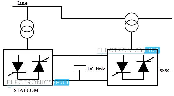
UPFC is the combination of STATCOM and SSSC which are coupled by via a common DC link. It can exhibit the characteristics of both SSSC with series voltage injection and STATCOM with shunt current injection, with added features. It has a unique ability to perform independent control of real and reactive power flow. Also, these can be controlled to provide concurrent reactive and real power series line compensation without use of an external energy source. In the above UPFC, SSSC (or converter-2) injects a voltage with controllable magnitude and phase angle in series with the line though a series transformer. The function of STATCOM (or converter-1) is to absorb or supply the reactive power demanded by SSSC at the common DC link. It can also supply or absorb the controllable reactive power to the transmission line to provide independent shunt reactive compensation.
Thyristor Controlled Series Capacitor (TCSC)
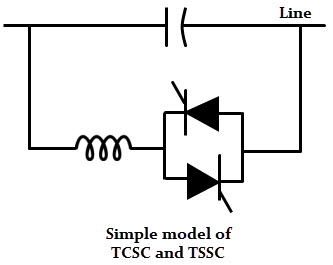
It is a capacitive reactance compensator. It consists of a series capacitor bank which connected in parallel with a thyristor controlled reactor that provides a smooth variable series capacitive reactance. The total impedance of the system can be varied by changing the conduction angle of the thyristors and hence the circuit becomes either inductive or capacitive. If the total circuit impedance is inductive, the fault current is limited by this controller. A simple model of TCSC is shown in figure below.
Thyristor Switched Series Capacitor (TSSC)
Similar to TCSC, it is also a capacitive reactance compensator consisting of thyristor switched reactor in parallel with a series capacitor. It provides the stepwise control of series capacitive reactance. Instead of controlling in continuous manner, it switches the reactor such that the thyristors are fired at 900 and 1800. This controller can be implemented without firing angle control to reduce the cost and losses.
Thyristor Controlled Series Reactor (TCSR)
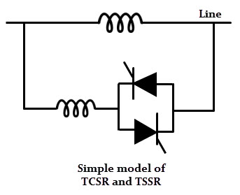
It is an inductive reactance compensator which consists of a series reactor in parallel with thyristor switched reactor. This controller provides a smooth variable inductive reactance. When the thyristors firing angle is 1800, the reactor stops conducting and hence the uncontrolled reactor only is in series with the line that acts as a fault current limiter. If the firing angle is below 1800, the net (or overall) inductance decreases, thereby voltage is controlled in the network.
Thyristor Switched Series Reactor (TSSR)
Similar to TCSR, TSSR is also an inductive reactance compensator but it provides the stepwise control. This controller switches thyristors such that they are either fully ON or fully OFF in order to achieve stepped series inductance.
Interline Power Flow Controller (IPFC)
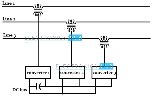
It is the new technique for effective power flow and compensation management of multiline transmission systems. It consists of a number of converters which are connected with a common DC link and each converter is provided for series compensation for a selected transmission line. In addition to the reactive power compensation, this controller can able to transfer real power among the transmission lines due to a common DC link. So it is possible to equalize both real and reactive power between the lines.
Thyristor Controlled Phase Shifting Transformer (TCPST)
It is a variable phase angle controller, which consists of thyristors and phase shifting transformer. The variable phase angle control is achieved by switching the thyristor for different conduction angles. Comment * Name * Email * Website
Δ





![]()