A sinusoidal quantity, say a voltage can be expressed as V = Vm sin (ωt + θ) Where V = instantaneous value of the voltage Vm = maximum value of the voltage ω = angular velocity = 2π f θ = Phase angle The basic elements of an AC circuit are resistance, inductance and capacitance. AC circuits use the combination of these elements (any two or three) in series and parallel combinations. The operation of an each individual circuit with individual elements is different from the circuit which consists of combination of these elements. In this article we are going to discuss the behavior of AC circuit with resistive load.
AC Applied Across a Pure Resistor
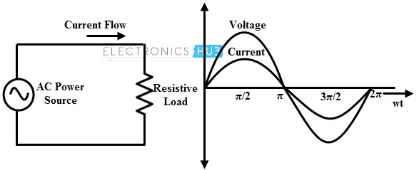
In this, a pure resistance is connected to the AC supply source which is equivalent to the circuit that supplies the AC power to a resistor or a lamp or a heater or any other resistive load. It is the simplest type of AC circuit that doesn’t have any inductance or capacitance. This pure resistive circuit behaves like a DC circuit by offering the same type of opposition to the AC current that in case of DC current. The figure below shows AC resistive circuit with voltage and current waveforms.
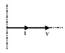
When an AC voltage is given to the resistive load, current through the circuit varies with the voltage applied and this current value can be determined using Ohm’s law. This current magnitude depends on the effective values of applied voltage and resistance in the circuit. Let the instantaneous value of voltage, v = Vm sin ωt Then, the current through the circuit according to the Ohm’s law is given as i = V/R = Vm sin ωt / R At ωt = 900 the value of i is Im, therefore, Im= Vm/R Thus the current can be written as , i = Im sin ωt Therefore, both voltage and current waveforms are sinusoidal in shape and also have same frequency. This means that the current direction varies in the same manner of applied voltage and hence they are in phase with each other. Thus, voltage and current waveforms reaches their maximum and minimum values at the same instants. However, the amplitudes of these waveforms are different from each other. The phasor representation of an AC resistive circuit is shown below in which current and voltage waveforms are in phase.
Power and Power Factor
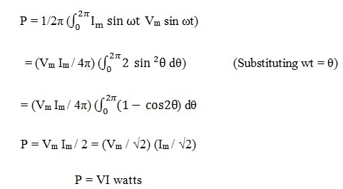
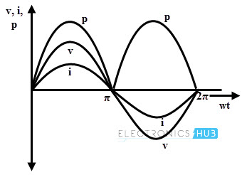
The power in the resistive circuit is the product of voltage and current. The average power in an AC resistive circuit can be calculated as
Since there is no phase difference between the voltage and current waveforms, phase angle is zero (θ = 0) and thereby power factor will be unity. Power factor, cos θ = cos 00 = 1
Example 1
If the circuit has an AC voltage source of 280 V and heating element of 40 Ohms, what is the effective current drawn from the supply? And also determine the power consumed by the heating element. Current drawn from the supply, I = V/ R = 280/ 40 = 7 amperes And the Active power consumed by the AC resistance is P = i2 R = 42 ×60 = 960 watts Example 1 for Resistive AC Circuit If an AC sinusoidal voltage of V (t) = 200 x cos (ωt + 600) is connected across a resistance of 40 Ohms, then what is the current flowing through the circuit? Converting the given voltage expression from the time-domain into the phasor-domain. We get VR (t) = 200 cos (ωt + 600) → VR = 200 ∠600 volts By applying Ohms Law, the current through the circuit can be calculated as IR = VR / R = 200 ∠ 600 = 200 ∠ 600/40 = 5∠ 600 amps
Series AC Circuit with Resistive Loads
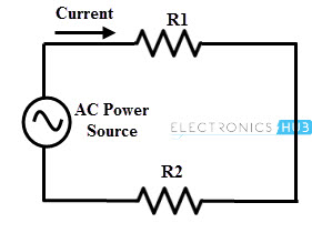
The figure below shows the simple AC circuit consisting of a series connected resistors across the supply. The current through each element or at any point in the circuit has same value due to the series connection and its magnitude depends on the applied voltage and total resistance in the circuit. Regardless of the number of series connected resistors, the current always in phase with the applied voltage.
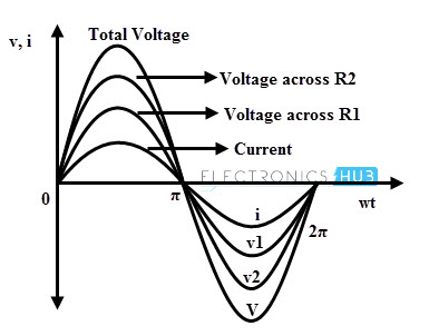
In the above circuit, voltage across the each resistance can be determined by applying the Ohm’s law. The sum of the voltage drops across each resistance gives the total voltage applied to the circuit. The phase relationship between the applied voltage and current of this circuit is illustrated in the below diagram where both individual voltage drops and total voltage are in phase with current.
Example
Suppose, if the circuit has an AC voltage source of 280 V and two heating elements of 40 Ohms and 60 Ohms respectively, then what is the voltage drop across each heating element. The total resistance in the circuit, RT= R1 + R2 = 40 + 60 = 100 Ohms The current flowing through the circuit, IT = V/ RT IT = 280/ 100 = 2.8 A Therefore, IT = IR1 = IR2 Then, Voltage drop across heating element-1, V1 = IT R1 = 2.8 × 40 = 112 V Voltage drop across heating element -2, V2 = IT R2 = 2.8 × 60 = 168 V
Parallel AC Circuit with Resistive Loads
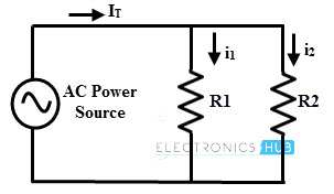
In parallel AC circuit, various resistive loads are connected across the AC voltage source, so the voltage across each branch remains constant while the total current distributes among the individual resistive branches. Therefore, the total current can be determined by adding all individual currents flowing through each resistance. These individual currents are in phase with the applied voltage as the circuit consisting of pure resistive load.
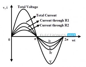
The above figure shows the in-phase relationship between the voltage and individual currents in a parallel AC circuit having a pure resistive load. The magnitude of individual current through a resistor depends on the voltage applied and the resistance offered by that resistor. If the resistor has more value, the current flow through it will be less and vice-versa. However, these currents follows the voltage waveform (i.e., in phase with it) regardless of their magnitudes.
Example
If the circuit has an AC voltage source of 240 V applied across two parallel heating elements of 390 ohms and 1k Ohms respectively, then what is the effective current flowing through each of the heating elements? In parallel circuit, voltage across the each resistor is same, i.e., V = V1 = V2 According to Ohm’s law, current through heating element-1, IR1 = V1 / R1 = 240/390 = 0.615 = 615 mA Similarly, IR2 = V2 / R2 = 240/1000 = 0.24 = 240 mA Therefore the currents through heating elements are 615 mA and 240 mA respectively. Comment * Name * Email * Website
Δ
![]()
![]()
![]()
![]()
![]()

